Tij
Vishwakarma


Mechanical Robotics Engineer


Jaia Robotics, Inc.


MS. Ocean Engineering
BS. Aerospace Engineering

tij2.webp
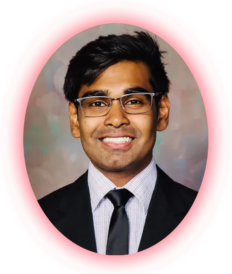
Hi, my name's Tij and I am a Mechanical Robotics Engineer at Jaia Robotics Inc. I have a combined experience of 3+ years, with a proven history of professional and academic excellence, as highlighted through this portfolio. Currently, I am open to new opportunities across the United States. Let's talk! tij2heehee.webp
Projects Timeline

Co-Author

Coming Soon

Underwater Hydroacoustic Textbook

Outstanding Student of the Year

2024

Florida Tech

Mechanical Design Engineer

May 2023 - Present

Catania Product Development

Post Graduate Instructor

January 2023 - May 2023

For OCE 5093 : Computational Fluid Dynamics (CFD) For Ocean Eng. at Florida Tech


Phi Kappa Phi Scholar

Post Graduate Instructor

August 2022 - December 2022

  • For OCE 2002 : Computer Applications In Ocean Eng. at Florida Tech
  • Building My Online Portfolio

  • Amazon Prime Video Feature

    The College Tour S01E02

    Phi Eta Sigma Scholar

    Graduate Researcher

    January 2021 - December 2021

  • CFD Force & Stability Analysis of a Towfish
  • Scientific Cruise: R/V W.T. HOGARTH
  • Scientific Regression Analysis & Resistance Eq. Development

  • Post Graduate Grader

      Post Graduate Student Grader for AEE 4262: Rockets & Mission Analysis

    Undergraduate Researcher

    October 2019 - May 2020

    Tank Diaphragm Analysis

    Undergraduate Researcher

    May 2018 - January 2020

    The Flying Fish Amphibious UAV

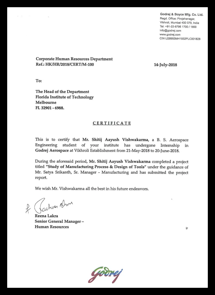
    Manufacturing Intern

    May 2018 - June 2018

    Manufacturing Process & Design of Tools Internship at Godrej & Boyce Mfg. Co. Ltd.

    Senior Design Capstone Project

    January 2017 - May 2018

    Nautilus Amphibious UAV/AUV

    Recent Projects

    01
    & Experience
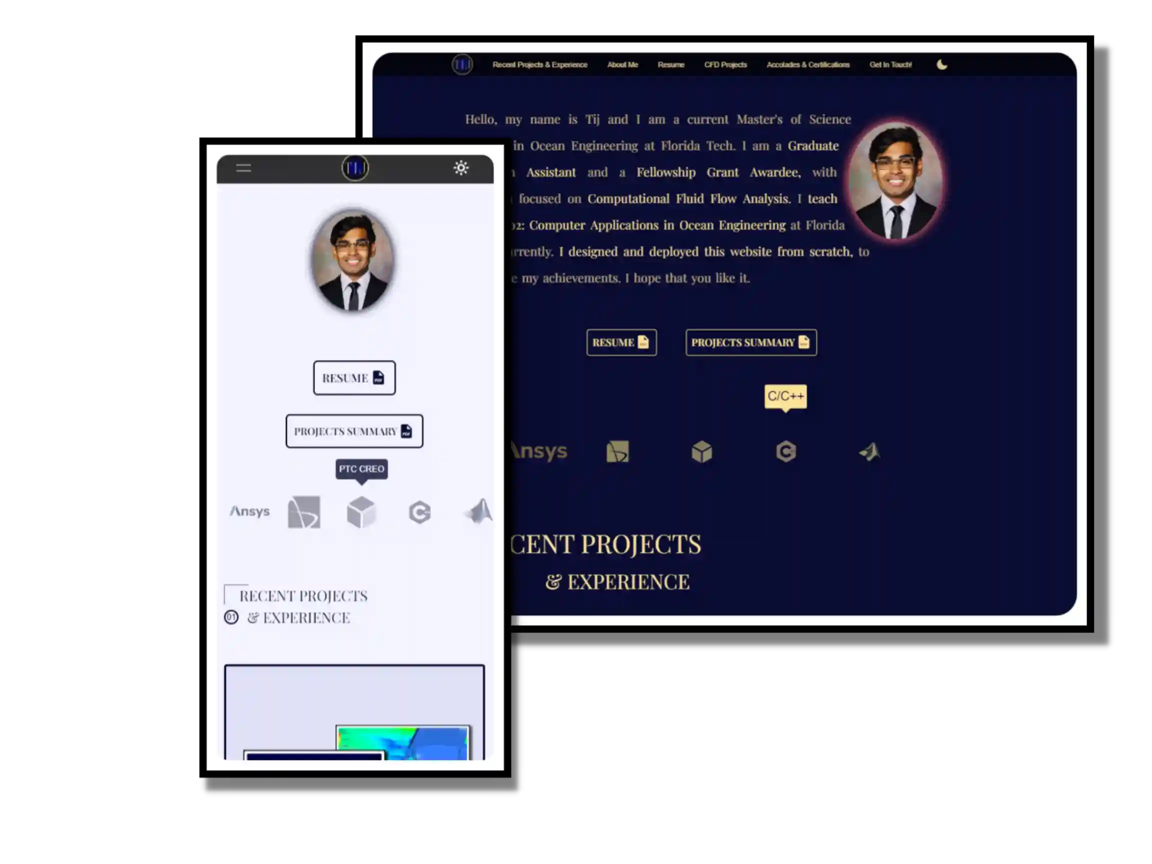
    My Online Portfolio Website
    HTML, CSS, JavaScript


    My Online Portfolio


    Overview


    An ambitious, personal project of mine that started as an idea to store all my achievements in one place. The two criteria it needed to meet were that it must be:

         1. Easily accessible from anywhere, at any time, on anything.

         2. Be responsive across all platforms, without the loss of quality and user experience.

    Consequently, I decided to buy the domain name tijvishwa.com, host it, and design the webpage for it. Initially, I opted for a template to design the portfolio. But soon, after being frustrated from the lack of quality, I chose to learn HTML, CSS, and JavaScript from scratch to create this portfolio in my vision. The result is what you see, in front of you.

    Everything you can and cannot do has been meticulously hard-coded!


    Method


    Admittedly, this was one of the most challenging projects I have worked on because I had no prior experience with front-end development. Having no guidance except that from the online resources, the task was particularly challenging. However, the result of persistent hard work is that this website successfully incorporates and integrates PopState Events, PushState Events, hashing, links-integration, dialogs, transitions, dark-theme/light-theme switching, download links, animations, media queries, pseudo-classes and pseudo-elements, view-all scripts, animated timeline, object comparison, callback functions, Immediately Invoked Functions Expressions (IIFE), background behavior, hamburger-menu in smaller screens, text-wraps (shape outside), and a lot more to create a seamless, cross-platform, responsive user interface. Don’t take my word for it, though… Give it a try yourself!


    Website View (Dark Theme)

    Website View (Light Theme)

    Mobile View: (a) Hamburger Menu View (Dark Theme);
    (b) Contact Form and Social Links (Light Theme)


    CFD Force & Stability Analysis of a Towfish
    ANSYS FLUENT, STAR CCM+, SIMERICS MP


    CFD Force & Stability Analysis of A Towfish


    Overview


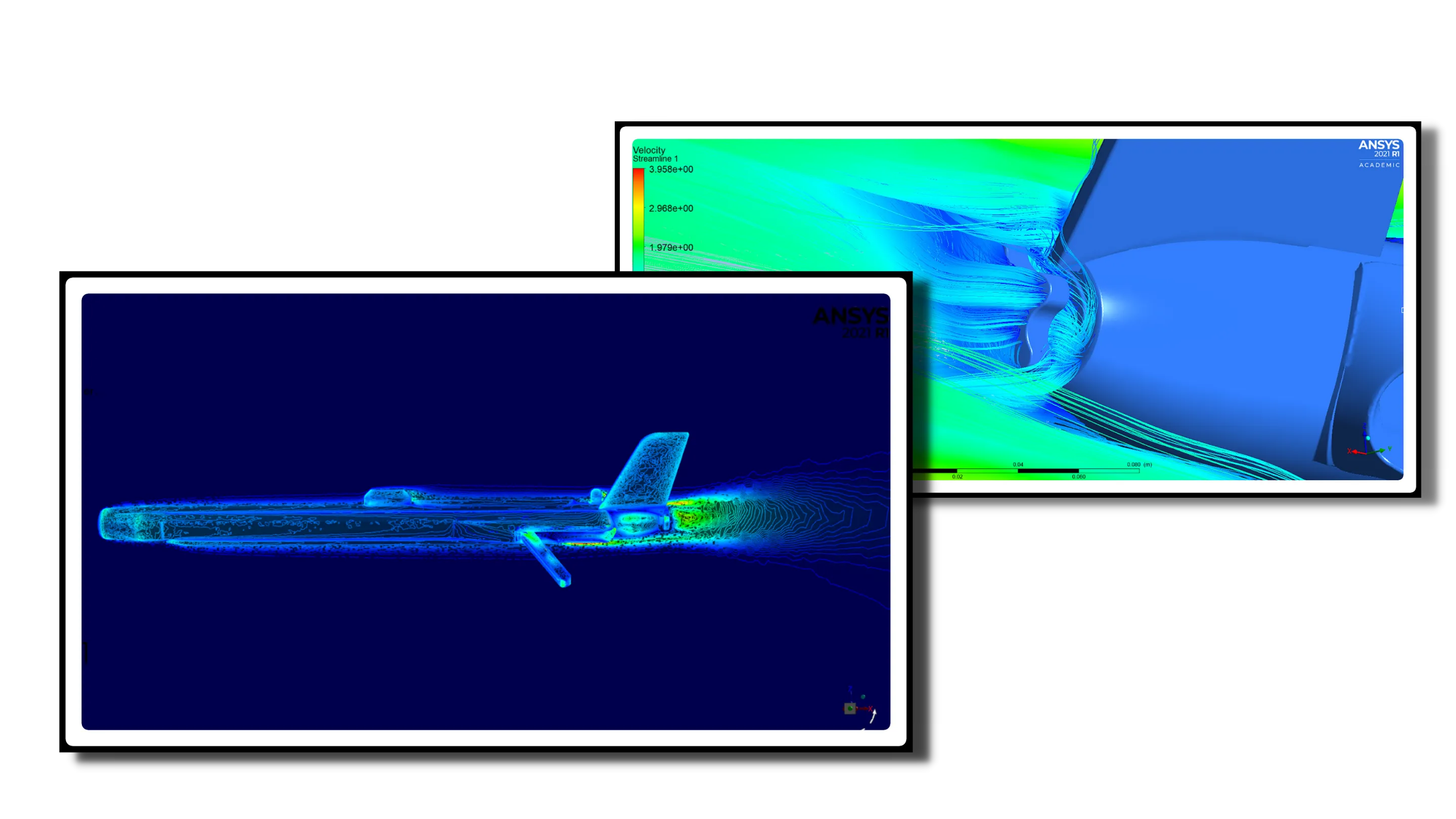
    Collaboration between Florida Tech and Mind Technologies Inc., to calculate the force and hydrodynamic stability of a Klein side-scan sonar, using Computational Fluid Dynamics (CFD) analysis. The goal was to identify the turbulent areas and modify the design to improve the hydrodynamic stability of the Towfish.


    Method


    In order to establish scientific validation to our results, we used three platforms: ANSYS Fluent, Star CCM+, and Simerics MP. The simulations ran independently, under the same working environment to establish baseline results, and to validate our findings.


    Model Used in Simerics MP


    Model Used in ANSYS and STAR CMM+


    Simulation Properties


    The Enclosure and The Mesh

    ANSYS Fluent

    ANSYS Fluent Simulation Enclosure with Inlet (Blue) and Outlet (Red)

    Display of Polygonal / Hexahedral Elements and Mesh Density in ANSYS Fluent


    Results


    The goal of Phase 1 was to establish scientific validation to our approach by obtaining the same baseline results across all three software. This validation would allow us to choose a singular software to proceed further to Phase 2: Design Improvement. Phase 1 was concluded successfully, with the results obtained cross-platform establishing scientific validation. Not only were we able to compare the results between the three software to each other, we were also able to compare filed test results to the ones obtained by Simerics MP. The following graphs discuss the same:

    Field Test Data vs Simulation Results

    Test Summary


    Sample Data from Test 2 Results


    Pressure & Velocity Results


    Flow Velocity Flux Around the Tailcone


    Pressure Distribution Around the Towfish

    Closing Comments


    Phase 1 was successfully completed after the submission of our results. The data obtained through our analysis gave MIND Technologies Inc. an insight to the turbulent zones in their model. The lift and drag force data helped them quantify this visual representation.


    Flow Flux Distribution

    Scientific Regression Analysis
    TIBCO STATISTICA, MATLAB
    Scientific Cruise: R/V W.T. HOGARTH
    KLEIN MARINE SYSTEMS, INC., JW FISHERS


    Scientific Cruise: R/V W.T. Hogarth


    Overview


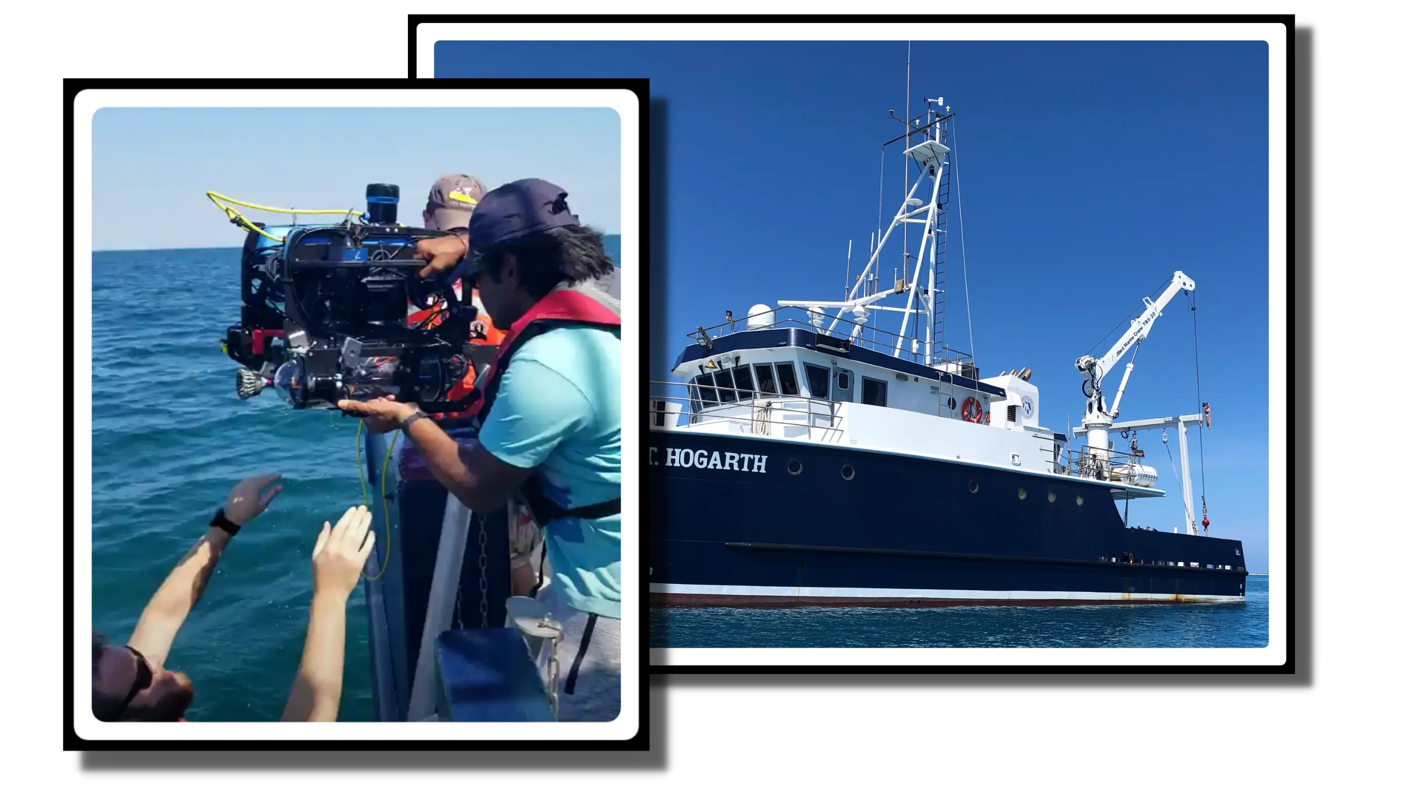
    The Department of Ocean Engineering at Florida Tech hosts scientific cruises for their seniors and graduate students every summer. The cruise sets sail from the Tampa Bay area and travels down the west coast of Florida to the Florida Keys then back up to Miami from the east coast of Florida. During this time, we deploy measuring instruments like magnetometers, side-scan sonars, underwater Remotely Operated Vehicles (ROVs) and take measurements of the seabed topography, shipwrecks, and the marine life. We also dive underwater, near the Dry Tortugas National Park, to explore the marine life and to explore the area.


    Experience and the Learning Outcomes


    Throughout the cruise I got to experience deploying the Klein 600 sonar, JW Fisher’s Proton 5 Magnetometer, and the Blue ROV2. I also got to maneuver and explore the Windjammer shipwreck by the Loggerhead Reef, at the Loggerhead Key. I learned the maritime code of conduct while being onboard, and also learned the procedure of onboard deployment and retrieval. But most of all, I loved the scenic, tranquil views of the ocean.

    Everyday Tasks Involved Deployment and Retrieval of Various Underwater Instruments


    (a) Retrieving Blue ROV 2


    (b) Momentarily Ship Heading


    Fort Jefferson Photo Op!

    (a) Braidan Explaining the Deployment Protocol to Me
    (b) Me Deploying the Proton 5 Magnetometer

    (c) Proton 5 Detecting Objects On the Ocean Floor


    Side-Scan Sonar


    The Blue ROV 2 with the Spool and the Tether


    Sunset Over Fort Jefferson in the Dry Tortugas National Park


    The Flying Fish Amphibious UAV/AUV
    RHINO 3D, PTC CREO, STAR CCM+


    The Flying Fish Amphibious UAV/AUV


    Overview


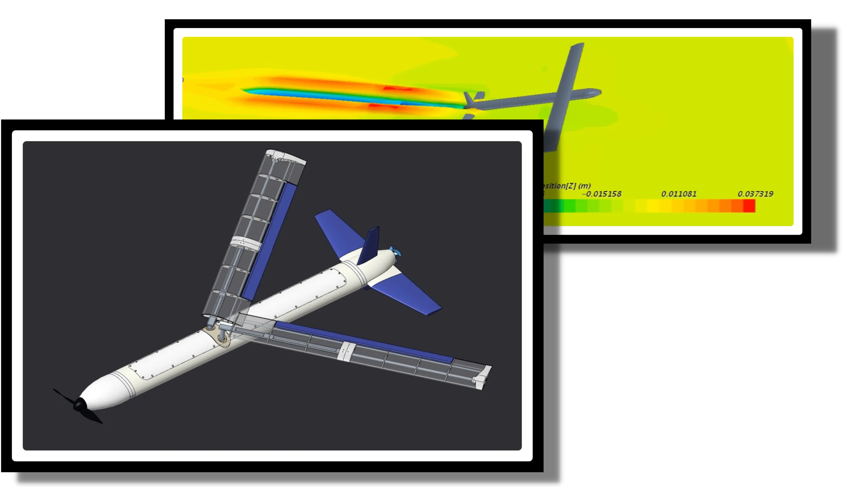
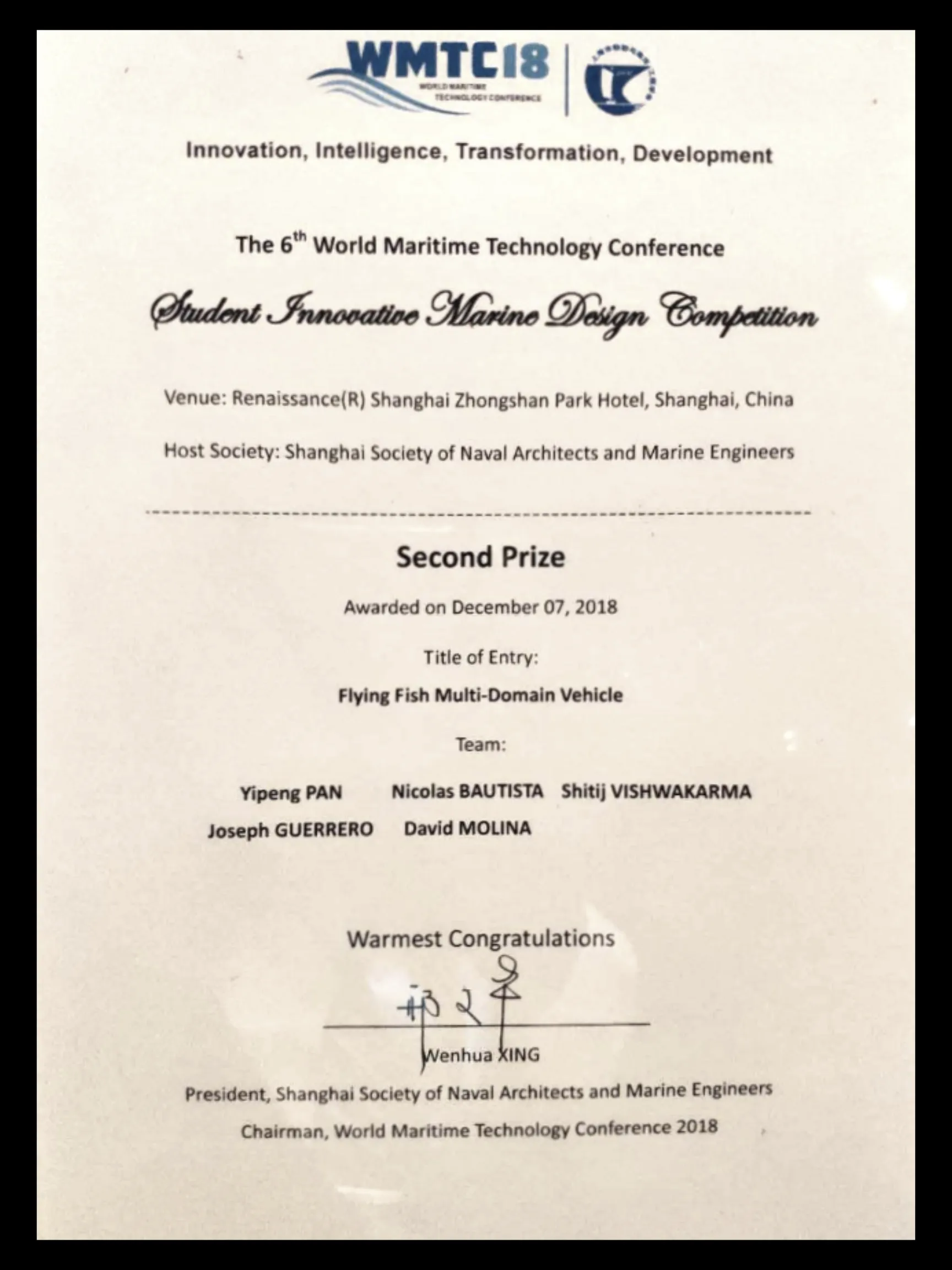
    Follow-up project to the Nautilus, but under the Department of Ocean Engineering at Florida Tech. While the core principles and research were kept the same, this iteration underwent a complete redesign. The weight was reduced, thanks to better 3D printed material, hydrofoils were integrated to assist during lift off, and a waterjet nozzle was deigned specifically for underwater maneuvering. Our efforts were recognized at the 6th World Maritime Technology Conference, where the Flying Fish came in Second place in the Student Innovation Design Competition.

    One of the Iteration for the Flying Fish


    Method


    Being a follow-up to Project Nautilus, the core, preliminary research done for Nautilus carried over. Consequently, the new design incorporated the same systems architecture as the Nautilus, but also improved upon the underwater and in-water maneuverability. With the help of Dr. Yang and Dr. Wood from the Department of Ocean Engineering, the redesign was better hydrodynamically.

    Take-off Sequence Visualized


    Rhino-3D Rendering


    Crediting to the new ballast tanks which doubled as hydrofoil chambers, we were able to achieve varying bouncing during each stage of the takeoff – A, B, C, and D. Furthermore, the wing design was also tested by the team inside a wind tunnel to verify the wind-test data and behavior.

    Testing the 3D Printed Wing Cross-section in a Wind Tunnel


    During our design stage, the team ran CFD simulations to test the viability of a good field run, in Star CCM+.

    Simulating the Viability of the New Design in STAR CCM+


    This data was then verified by the Cl and Cd performance. The redesign served as a tool to strengthen our hydrodynamics and get one step closer to a successful prototype:

    Final, and Successful Iteration of the Flying Fish+


    Nautilus Amphibious UAV/AUV
    MATLAB, PTC CREO, STAR CCM+


    Nautilus Amphibious UAV/AUV


    Overview


    Senior Design CAPSTONE project in the Aerospace Engineering, that attempts to bridge the gap between air and sea travel by targeting the development of a Multiple-Domain Vehicle (MDV) capable of long duration aerial, surface, and underwater activities. This project focuses on the development and verification of an unmanned MDV capable of operating underwater, on the sea surface and in air with transitions between mediums. These transition capabilities combined with the high aerodynamic and hydrodynamic efficiency and reliability of a folded fixed wing unmanned aerial vehicle (UAV), result in a technology that can extend operations, provide rapid response, and adds new capabilities in the ocean battlespace environment.


    (a) Nautilus with the Wings Deployed

    (b) Nautilus with the Wings Retracted


    Mission Requirement Flow Diagram


    Method


    Being a CAPSTONE project, Project Nautilus was divided into two stages:
        1. Preliminary Design Review (PDR)
        2. Critical Design Review (CDR)


    Preliminary Design Review (PDR)


    During this stage, we established the System architecture and the baseline technical design assessments.

    System Architecture for Nautilus


    The technical design assessments included preliminary CAD model iterations, structural Finite Element Analysis (FEA) in ANSYS, power calculations, communications designs, Aerodynamics calculations in XFLR5, and CFD simulations in STAR CCM+.


    (a) First Design Iteration for Nautilus

    (b) Final Design Iteration for Nautilus


    (a) FEA on Nautilus in ANSYS Mechanical

    (b) CFD Analysis on Nautilus in STAR CCM+

    (c) CFD Analysis on Nautilus in STAR CCM+


    Controls Diagram for Nautilus

    Motor Power Requirement Calculations

    Wing Lift and Drag Analysis in XFLR5


    Critical Design Review (CDR)


    At this stage, we evaluated and verified the data gathered during the PDR stage by constructing a working prototype. This prototype was made from a mix of the fiberglass composite, 3D printed PLA, and Aluminum 6061.

    (a) The Linear Actuator and the Internals

    (b) Wing Spars

    Final, Finished Iteration of Nautilus

    Members of the Nautilus Team


    Internship: Manufacturing Process & Design of Tools
    Godrej & Boyce Mfg. Ltd. Co., India


    Manufacturing Process & Design of Tools


    Overview


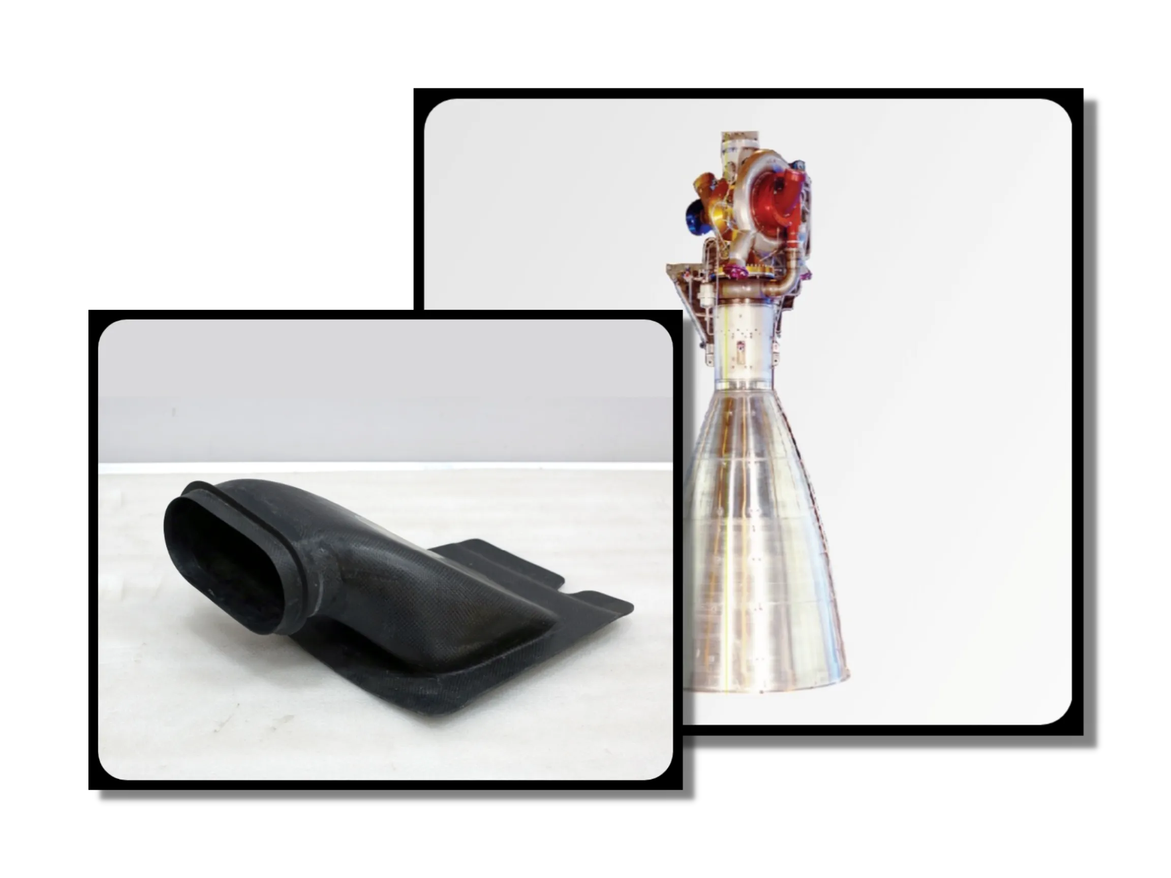
    During my internship at one of the plants at the Godrej & Boyce Mfg. Ltd. Co., Mumbai, India, I learned about the basics of GD&T. One of the first tasks was to learn and understand the basics of “Drawing Reading”. This referred to the reading and interpretation of engineering drawings, for parts that went inside the rocket thrusters and nozzles.
    I started off by learning about symbols of straightness, circularity, parallelism, concentricity, etc., to learning about the difference between First- and Third angle views, to the types of lines -Object, Dashed, Center, Phantom, and Break. Then I learned about the different categories of dimensioning: Continuous, Baseline, Staggered, and Ordinate. During my finals days, I learned about teh various furnaces the plant utilized for heat treatments: Vacuum furnaces, Galvanizing furnaces, and Tempering furnaces. My study included learning about each furnace's specifications, pyrometry details as per ASM 2750E, it's process scope, and it's material scope.
    I ended my internship by submitting a detailed report of all my learnings and understandings. This was reviewed and approved by my supervisor. Consequently, I was awarded the certificate of completion by Godrej & Boyce Mfg. Ltd. Co.


    Nautilus Amphibious UAV/AUV
    MATLAB, PTC CREO, STAR CCM+
    Nautilus Amphibious UAV/AUV
    MATLAB, PTC CREO, STAR CCM+
    Nautilus Amphibious UAV/AUV
    MATLAB, PTC CREO, STAR CCM+

    ABOUT

    02
    ME

    Going into my Master's degree, I wanted to become a well-balanced professional. Hence, while my current area of research is Computational Fluid Flow Analysis, my skill-set includes:

    ANSYS FLUENT STAR CCM+ SOLIDWORKS
    SLA/SLS 3D Printing PTC CREO C/C++
    MATLAB FLOW 3D JIRA
    HTML CSS JavaScript

    These skills and experiences helped me lead the various projects showcased in this portfolio. Lastly, I also owe my success and growth to Dr. Stephen Wood. I am forever grateful for his support and faith in me.

    I can be reached via email or cellphone. Both of which are in my resume, for security & privacy reasons.
    Graduate

    03
    CFD Projects
    CFD Force & Stability Analysis of a Towfish
    ANSYS FLUENT, STAR CCM+, SIMERICS MP
    Heat Conduction Dissipation Simulation on a 1-D and a 2-D Wall
    C/C++, MATLAB


    Heat Conduction Dissipation Simulation on a 1-D & a 2-D Wall


    Overview


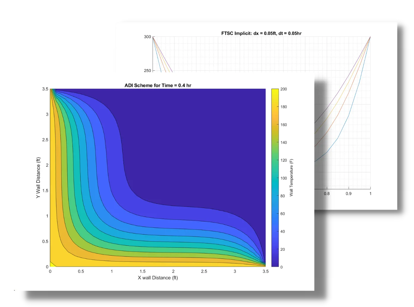
    Simulation in C and MATLAB to capture the conduction of heat on 1-D and 2-D walls. For calculations, we implement the 1-D and 2-D Heat equations, respectively. In the first part, I compare the efficiency of various computation methods, viz:

    1.  The Crank-Nicolson Method
    2.  The DuFort Frankel Method
    3.  The Forward in Time, Center in Space [FTCS] Implicit Method
    4.  The FTCS Explicit Method,

    on a 1-D wall, with plots as a visual guide for accuracy.
    In the second part, I use the said techniques to display dissipation of heat across a 2-D wall; again, verified by 2-D plots for times 6 minutes and 24 minutes, respectively. The simulation ran for up to T = 0.5 hours.

    NOTE: To review the C source code and MATLAB contour plots, please visit my GitHub.


    Results & Discussion


    Part 1: 1-D Wall

    Sample Results: The DuFort Frankel Method


    1-D Heat Progression for delta t = 0.01hr


    1-D Heat Progression for delta t = 0.05hr


    Part 2: 2-D Wall


    In this part we discretized and solved the 2-D Heat Conduction Equation:


    Where α is the thermal diffusivity.

    Results for Part 2


    2-D Heat Progression after 6 minutes


    2-D Heat Progression after 24 minutes

    Streamline Flow Flux Simulation on a 2-D Wall
    C/C++, MATLAB


    Streamline Flow Flux Simulation on a 2-D Wall


    Overview


    Simulation in C to capture the stream inflow behavior, given the wall conditions. This program implements the 2-D, incompressible flow, continuity partial differential elliptical equation to solve the problem:


    In the following domain:

    Discretization of this equation is done by implementing various computational numerical schemes:

          1. Line Gauss-Seidel Method
          2. Point Gauss-Seidel Method
          3. Line Successive Over Relaxation Method (LSOR)
          4. Point Successive Over Relaxation Method (PSOR)

    As a subtask, I also compared how soon each of the aforementioned methods solved the problem. This is represented in the number of iterations given on each of the corresponding plots.


    Results & Discussion


    Below, is the graphical representation of the iteration count point at which the program diverges and gets stuck in an infinite loop. The simulation runs until the convergence criteria of Max Error < 0.01 was met.


    Convergence Iteration Count


    Flow flux simulation is given by the sample plot below:


    Sample Flux Simulation for One of the Iterations


    Wave Behavior Inside a Closed Tube Simulation
    C/C++, MATLAB


    Wave Behavior Inside a Closed Tube Simulation


    Overview


    Part 1: Simulation in C to analyze shockwave propagation behavior inside a closed tube, using different numerical techniques. Namely:

        1. Forward in Time Backward in Space (FTBS) Explicit Method
        2. Lax-Wendroff Method
        3. Euler's Backward in Time Center in Space (BTCS) Implicit Method.

    Note: In this task, the simulation solely depends on the initial conditions and the boundary conditions. No particular governing model partial differential equations. As a subtask, I compared the effectiveness of each method at different time steps. The judging criteria were based on:
              3.1. The loss of wave amplitude
              3.2. The deformation of the wave shape over time. The simulation ran for up to T = 0.15 seconds.

    Part 2: Simulation in C to use MacCormack's Explicit Method to solve the Burger's Equation at different time steps:
         1. delta_t = 0.1
         2. delta_t = 0.2
    The simulation ran for up to T = 2.4 seconds. The results were plotted and then compared.


    Initial Shape of the Wave in the Closed Tube, at t = 0


    Results & Discussion


    Part 1: Sample Results


    Progression of the Wave Through the Tube, using the BTSC Implicit Scheme


    Part 2: Sample Results


    Solving the Burger's Equation using the MacCormack Method


    Mesh Generation Around an Airfoil
    C/C++, MATLAB


    Computational Mesh Generation Around an Airfoil


    Overview


    This is thus far my favorite coded simulation. For this simulation, not did we have to code an airfoil shape, but we also had to code the grid/mesh around it. This was particularly challenging because I had to connect all the points on the airfoil to all the points on the outer grid. This is plotted as the Algebraic Grid mesh. This was just the setup (initial condition).
    Once the setup was ready, I was tasked to code and apply the Line Gauss-Seidel or Line Successive Over Relaxation Methods to transform the current Algebraic Mesh into an Elliptic Mesh type. The advantage of this mesh type is an increase in the accuracy of the calculations and a decrease in the computing time. This was plotted as the Elliptical Grid Mesh, where when compared to its counterpart, the difference is obvious. Line Gauss-Seidel was applied for the sake of simplicity and the simulation ran until the Max Error < 0.01 criteria was satisfied.


    Results & Observation


    The following equation was used for the creation of the 2-D airfoil:


    Results:


    Before Applying the Elliptical Scheme


    After Applying the Elliptical Scheme


    Observations:


    After the scheme was applied, the mesh around the airfoil:
        1. Curves to the geometry of the airfoil;
        2. Is denser closer to the geometry of the airfoil than compared to the edges at the outer domain;
        3. The progression of each consecutive layer of the mesh is not constant - Before, the mesh lines were equidistant apart throughout the entire domain.


    Cavity-Driven FlowAnalysis
    C/C++, MATLAB


    Cavity-Driven Flow Analysis


    Overview


    Like all other projects, the Final Project was coded in C. First I had to develop the numerical schemes applicable to the Poisson's Equation, for the given boundary conditions. Poisson's Equation is given as:

    Note: The procedure and the derivation are described in detail, in the document named "Final Project Report.docx".
    This equation was derived for the cavity flow inside the following domain:


    Once the equations were derived, I had to code and solve the cavity-driven inflow condition so the vorticity effect needed in the flow can be produced. This is also detailed in the project report document. It is a 2-D enclosure with delta x and delta y steps = 0.00625.

    The velocity of the plate is given as 1 (units), with a Reynolds number of 1000. The Error Max < 0.001 is the given convergence criteria.

    The top plate is at 3350 pressure units. The pressure gradient at the left and the right plate is 0.

    The simulation ran for 15,000 iterations with a time step of delta t = 0.003 (ND) Line Gauss-Seidel was used for this simulation for the sake of simplicity, but at the price of computation time.
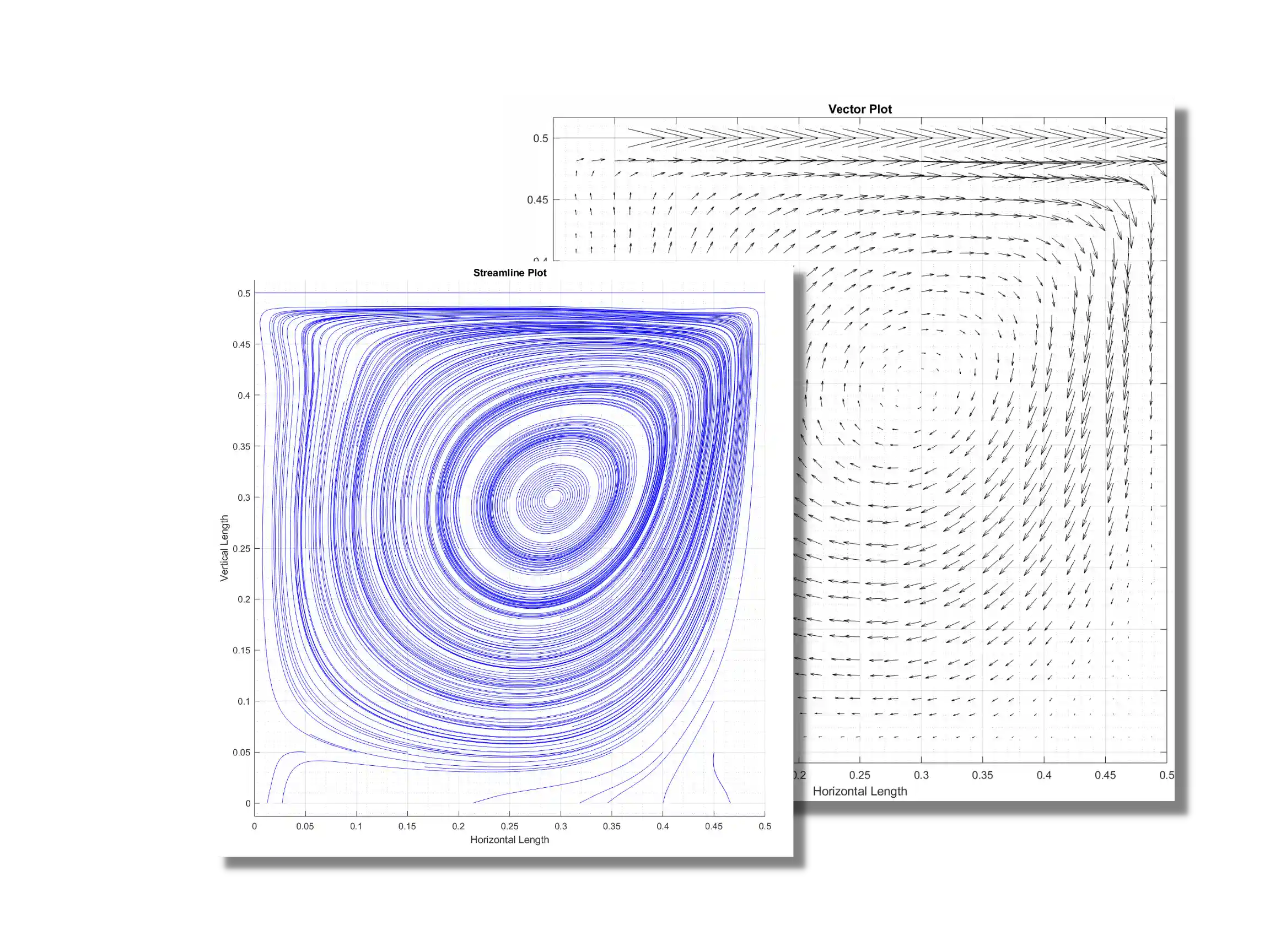
    Once the results were in, they were imported to MATLAB to create the streamline plots and the vortex plots presented.


    Results & Discussion


    Once the equation was derived and discretized to fit the give boundary conditions, the C-program I wrote solved them.
    After solving the equations, I used matlab to obtain the stream- and vector plots, below:


    Streamline plot of the Fluid Cavitation Inside the Domain


    Superimposed Vector Plot to Represent the Fluid Velocity at Each Point

    Discussion:


    The plots above represent the flow flux direction, velocity, and behavior in a domain while facing cavitation - a phenomenon very familiar to both Aerospace Engineers and Ocean Engineers. It is important to remember, however, that the "snapshot" above is describes the behavior at only one frame of time. Meaning, if the simulation was treated as an unsteady state problem, we would see the streamlines change and behave in accordance to the conversation laws of physics.


    Accolades

    04
    & Certifications

    Get In

    05
    Touch

    I am open to full-time opportunities! If you liked my work, let's discuss how you can benefit from my skills and experience!